


Lathe tools
Tools that are designed, fabricated and put to use on my lathe

Carriage stop
Goal
The component I designed is a carriage lock for a lathe. A carriage lock allows the carriage to be clamped at any position along the lathe bed, preventing movement through static friction.

Design
.jpg)
The part was designed in Fusion 360. My main constraints were the size of the aluminum stock on hand and the requirement that it be machinable using only a lathe and drill press. Thread diameter and pitch, tap holes, and clearance holes were referenced from the Machinery's Handbook and a standard drill tap chart. I chose ¼-28 threads because finer threads can handle greater clamping force and resist backing out due to vibration.
Creating parts
When designing the parts in Fusion 360, I used the facing surface as the reference for all measurements, since it is flat and perpendicular to the axis of the lathe bed.

For the bottom carriage stop, I started with a facing cut. I then turned down the shoulders to reduce the amount of material I would have to saw through. Since I don't have a milling machine, I used a hacksaw to cut off the edges and create a flat surface that rides in the gap between the lathe ways.

For the handle body, I took a rod slightly larger than ½ inch and turned it down to improve the surface finish. I then drilled a pilot hole using the correct size drill bit for a ¼-28 tap. Next, I took it to the drill press with the same bit to drill the handle hole, then tapped it.

For the handle itself, I turned down just the length needed for a ¼-28 3A major diameter. I then took it to the vise and used a die to cut the threads.
How i fit each part on the lathe
Fitting the part to the lathe was its own challenge. There were a lot of minor adjustments to make, and a few oversights where I could have designed the part better.
.jpg)
I started by taking measurements of the lathe. First, I used dial calipers to measure from the right side of the carriage to the left side of the right bed way, which came out to Y = 1.493 inches. Then I measured the gap between the ways, which came out to X = 0.4615 inches. Plugging these into (X/2) + Y gave 1.9587 inches — the distance from the right side of the carriage to the center of the gap. I also measured the diameter of the handle body and divided it by two, giving 0.251 inches.

Next, using layout fluid (Dykem Blue), dial calipers, and a scribing needle, I scribed the measurements onto the part. With a spring-loaded punch, I marked the intersection of the two scribe lines. I then removed the carriage from the bed and placed it in my drill press vise. I started with a center drill into the divot left by the punch, then drilled a through hole using the drill bit specified by the tap chart for a loose fit. Finally, I chamfered the hole for both appearance and ease of use.

When mounting the carriage stop onto the lathe, the first issue arose: the carriage lock interfered with the travel of the cross slide.


. I used various shims to change the angle at which the carriage lock engaged. After finding the right thickness, I drilled out the hole for the carriage lock shaft, sawed off the shaft to the length I needed, and filed it flush with the handle body.
Results
- Increased rigidity by reducing movement from 3 thou (when locking onto the lead screw) to 0 when using the carriage lock.
- Improved facing and parting accuracy by eliminating the need to lock onto the lead screw every 0.040"; the carriage lock provides secure clamping with zero movement.
Model ski lift
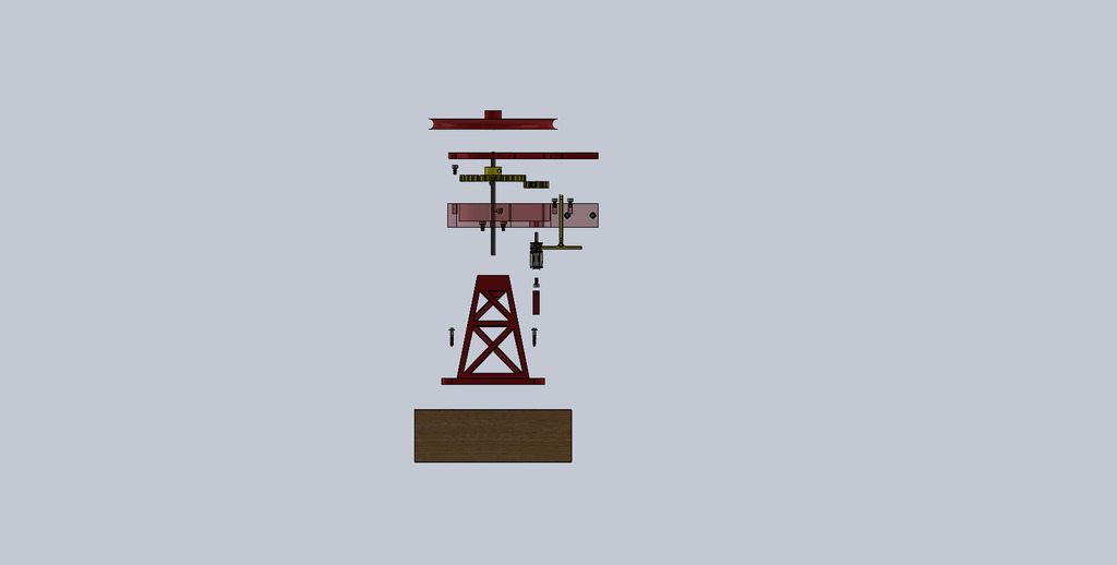
.jpg)
.jpg)
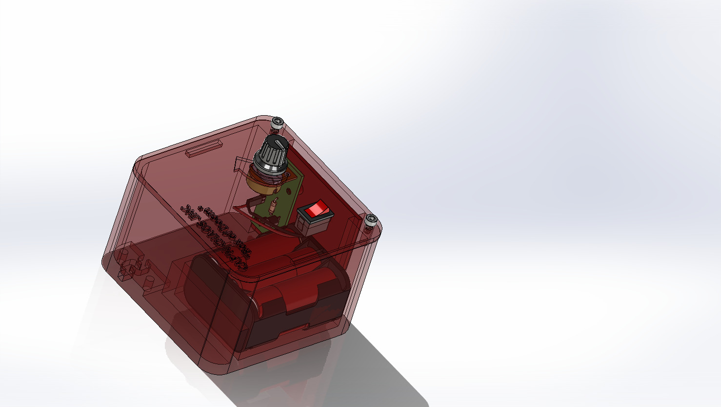
Have you ever wanted the power to send a letter, photos, or anything under one once across the room with a mild amount of waiting? Well, now you can.
Features
*Can carry small objects such as sticky note, pens, and polaroid pictures. *Can span across whole rooms and garages3D Printed Welding Brackets
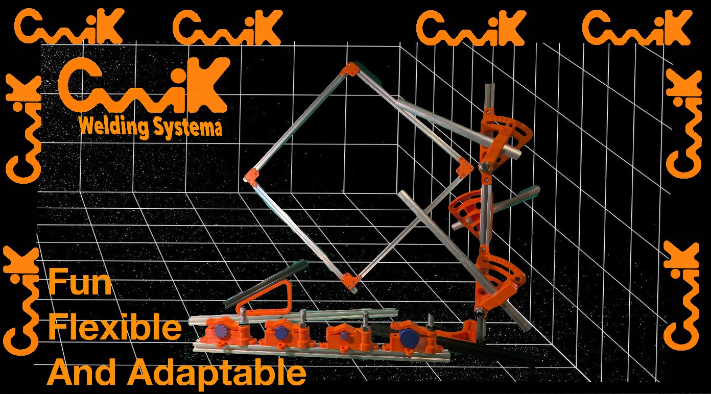
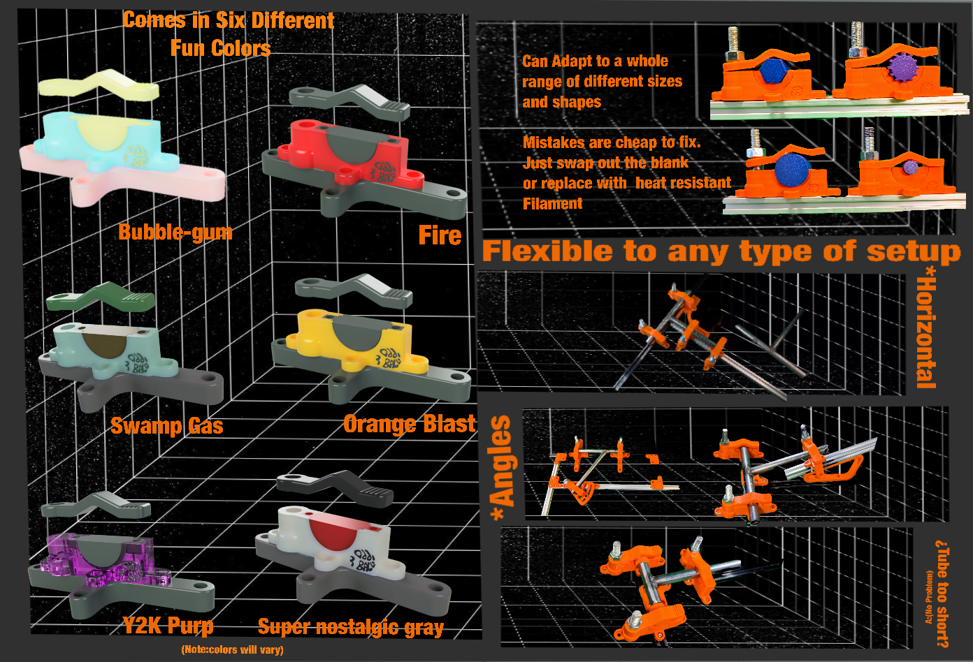
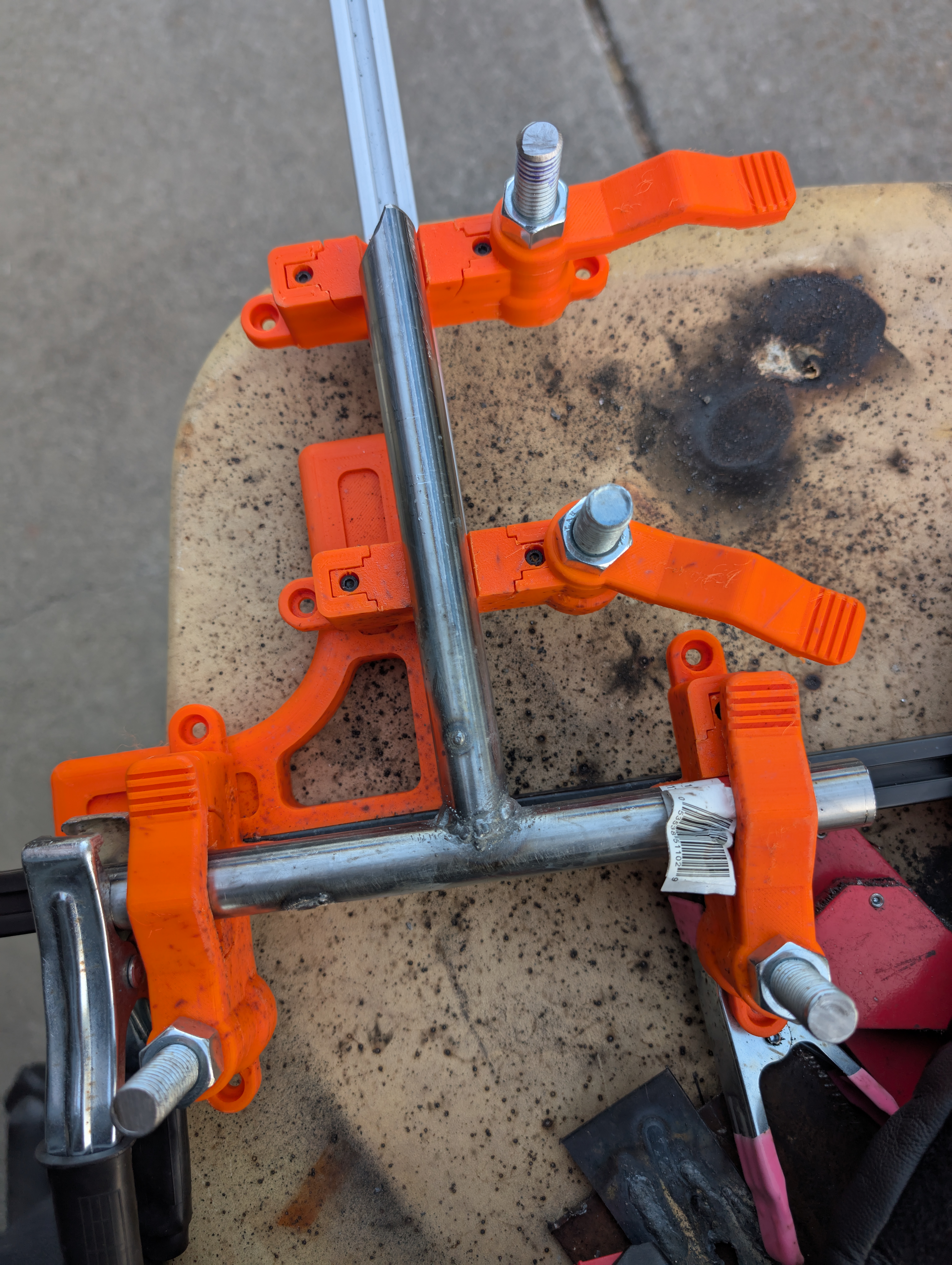
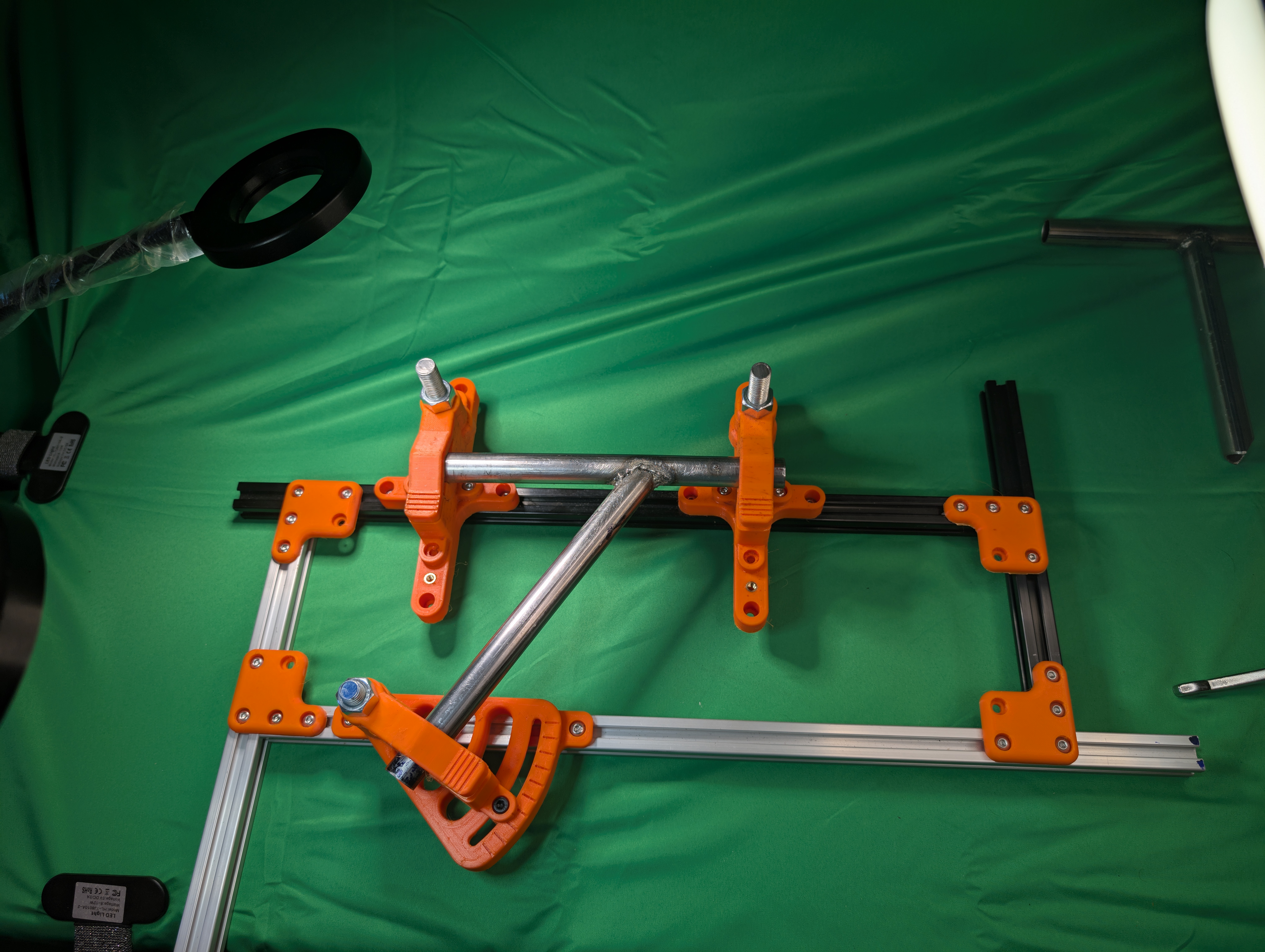
Welding jigs that could be used in various situations. Also, it was designed with the flexibility in mind of different types of tubing. 3D Print Files